Overview
This page proposes a minimal Linear Fractional Representation of the dynamic model of a satellite, composed of a rigid main body and two large flexible appendages. This benchmark is representative of challenges raised by the current and future space missions. More and more stringent requirements of pointing accuracy must be achieved despite high flexibility of the satellite structure. Usual synthesis methods of AOCS (Attitude and Orbit Control System) meet limits that can be circumvented by robust control design strategies [3,4,5].
A toolbox has thus been developed and enriched throughout studies in order to generate a structured linearized dynamic model [1] and its minimal Linear Fractional Representation [2,6] for any multi-body satellite configuration, where :
- the main body is supposed to be rigid ;
- appendages can be either rigid or flexible. Their joint to the main body can be either cantilevered or a pivot, driven by a mechanism ;
and uncertainties on
- mass/inertia of each body,
- flexibility characteristics (pulsations, dampings and modal participations) of appendages,
- tilt and/or inclination of appendages [6]
can be taken into account.
The originality of the approach is based on a linearized multi-body modeling, using the Euler's equations for each sub-system and aggregating them together by keeping explicitly physical parameters [1,6]. The toolbox is thus generic and allows to model any open chain of connected subsystems where flexibility can only be taken into account in the final body. Extensions are currently developed for open chains of connected flexible bodies.
This approach is today very useful to design the AOCS very early in the project (while the satellite is not yet accurately defined), to perform a co-design mechanics/attitude control and to simulation purpose. Current extensions will allow the generalization of the toolbox to high flexible polyarticulated arms (e.g. for space debris removal).
The proposed benchmark, that you can upload here, is derived from this toolbox (unavailable on this page). If you need more details do not hesitate to contact Christelle Cumer (christelle.cumer@onera.fr) or Thomas Loquen (thomas.loquen@onera.fr).
Few words on the multi-body approach
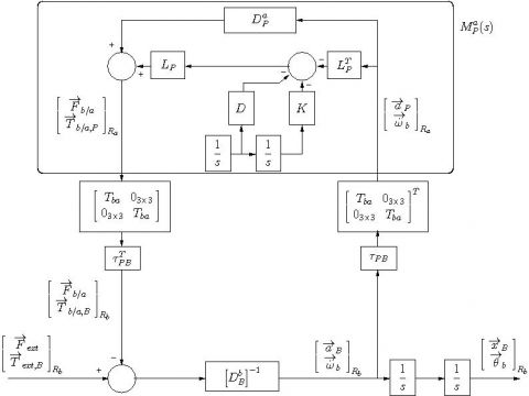
Satellite benchmarks, proposed here, are all composed of a rigid main body and flexible appendages. The Euler/Newton equations applied to the rigid main body (subscript $B$ refers both to the main body and its center of mass) give:
$$\left[ {\begin{array}{c} {\overrightarrow F _{ext} - \overrightarrow F _{\mathcal{B/A}} } \\ {\overrightarrow T _{ext,B} - \overrightarrow T _{\mathcal{B/A},B} } \\ \end{array}} \right] = D^{\mathcal{B}} _B \left[ {\begin{array}{c} {\overrightarrow a _B } \\ {\overrightarrow {\dot \omega }_b } \\ \end{array}} \right] $$
where the subscript $A$ refers to the "Appendage", $\overrightarrow F _{ext}$ and $\overrightarrow T _{ext,B}$ are the external forces and moments, $\overrightarrow F _{\mathcal{B/A}}$ and $\overrightarrow T _{\mathcal{B/A},B}$ are forces and moments due to the interaction with the appendage, and $ D^{\mathcal{B}} _B $ is the mass/inertia model matrix of the main body at point $B$ .
When the same equations are applied to flexible substructures (like a solar array), they become :
$$\begin{array}{l} \left[ {\begin{array}{c} { \overrightarrow{F}_{\mathcal{B/A}} } \\ { \overrightarrow{T}_{\mathcal{B/A},P} } \\ \end{array}} \right] = D^{\mathcal{A}} _P \left[ {\begin{array}{c} { \overrightarrow{a}_P } \\ { \overrightarrow{\dot \omega }_b } \\ \end{array}} \right] + L_P \ddot \eta \\ \nonumber \ddot \eta + diag(2\xi _i \omega _i) \dot \eta + diag(\omega _i ^2)\eta = - L^T _P\left[ {\begin{array}{c} {\overrightarrow{a}_P } \\ {\overrightarrow{\dot \omega }_b } \\ \end{array}} \right] \end{array}$$
where the subscript $P$ refers to the anchorage point between the appendage and the main body, $\xi _i$ and $\omega _i$ are respectively the damping ratio and the pulsation of the i-th cantilevered flexible mode of the substructure, $L_P $ is the modal participation factors of the cantilevered flexible modes computed at point $P$.
The contribution of the interaction forces/moments in both dynamic models can be modelled by a feedback, as highlighted by the block-diagram representation in Figure 1. Frame transformation matrices and kinematic models between different points are useful to connect the two dynamic models.
This modeling approach is clearly efficient for taking into account parametric uncertainties, while physical parameters are naturally extracted and minimally repeated.
Description of the benchmark
References
| [1] | D. Alazard, Ch. Cumer and K. Tantawi, " Linear dynamic modeling of spacecraft with various flexible appendages and on-board angular momentums", in 7th International ESA Conference on Guidance, Navigation & Control Systems, Tralee, Ireland, June 2008. |
| [2] | N. Guy, D. Alazard, Ch. Cumer and C. Charbonnel, "Modeling of Satellite Dynamics with Uncertainties", ESA GNC, Carlsbad, Czech Republic, 2011. |
| [3] | Th. Loquen, H. de Plinval, Ch. Cumer and D. Alazard, "Attitude control of satellites with flexible appendages: a structured $H_\infty$ control design", in AIAA Guidance, Navigation, and Control Conference, Minneapolis, United States, August 2012. |
| [4] | N. Guy, D. Alazard, Ch. Cumer, C. Charbonnel, "Reduced order Hinfinity controller synthesis for flexible structures control", IFAC ROCOND, Aalborg, Denmark, 2012. |
| [5] | N. Guy, D. Alazard, Ch. Cumer, C. Charbonnel, "New approach for AOCS design for a flexible satellite", ACA, Würzburg, Germany, 2013. |
| [6] | N. Guy, D. Alazard, Ch. Cumer, C. Charbonnel, "Dynamic Modeling and Analysis of Spacecraft With Variable Tilt of Flexible Appendages", in Journal of Dynamic Systems, Measurement, and Control, Vol.136, Issue 2, January 2014. |

